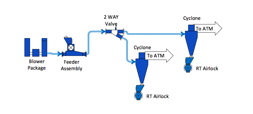
High pressure systems are conveyance systems, they convey large mass flows of product with a minimal amount of air long distances. Dilute phase high pressure systems are measured in PSI as the transport air is traveling at a high speed.
A positive displacement blower with inlet and discharge silencers creates the air required for material transport. A feeder assembly is an airlock and allows introduction of material into the high pressure system. The high pressure piping has a thicker wall thickness to handle the high air speed and wear. Flatback elbows are used when making a direction change as wear is a factor with speeds.
A valve assembly allows the high pressure system to direct material to multiple locations. The valve is a machined piece of equipment and capable of handling the pressures typical of high pressure conveying systems. Multiple ports deliver product to multiple locations, the valve cannot change ports unless the high pressure line is clear of product.

THE BLOWER PACKAGE
A positive displacement blower is the motive force creating air and pressure required to transport products through a heavy wall pipe. The blower and motor is selected specifically for the design parameters for a system. The blower requires an inlet and discharge silencer to attenuate the gear noise of the blower. The blower is mounted on a base which also includes motor and V-belt drive which powers the blower. After the discharge silencer, a pressure transducer is connected to the piping to sense pressure and provide signals to the plant PLC to protect the blower from an over-pressure event.

After

After
THE FEEDER ASSEMBLY
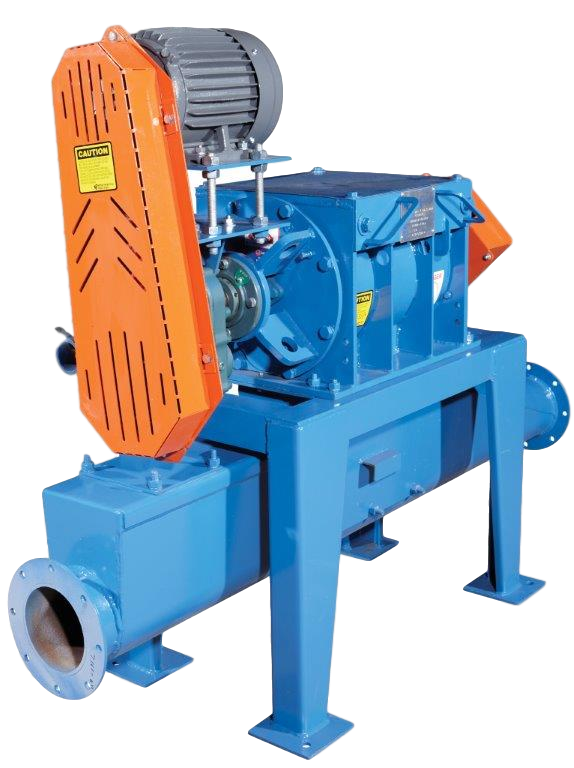
The feeder is an airlock and is the heart of the feeder assembly, robust in construction, tight tolerances between the rotating rotor assembly and the housing keep air from escaping.
The feeder assembly consists of a rotary airlock, drive, tee-injector and support base. Metered material is directed into the top of the feeder, the feeder internal rotor assembly rotates and allows material to be deposited into the tee-injector below. The feeder size is based on material volume passing through the feeder. The internal helical rotor assembly is constructed of thick steel blades, the ends of the blades have stainless steel overlay tips. The feeder internal housing is machined and chromed to extend the life of the feeder. A chipper quality knife is located at the top on one side and allows for shearing by the helical rotor blades.
A tee-injector is mounted directly below the feeder and allows material to fall from the feeder into an airstream created by the blower assembly. A base supports the feeder and the tee-injector, the centerline of the tee injector is typically 12” off the ground.
TWO WAY VALVE
A valve allows the high pressure system to discharge to multiple locations. The valve includes an inlet section with moveable transition and slip sleeve section to connect to a number of fixed ports. The ports are connected to high pressure piping headed to different destinations.
Material flow must be stopped prior to disengaging the slip sleeve section and moving the transition section to another port. High pressure system air discharges from the valve assembly when changing to different ports. When the linkage of the valve moves the valve into position, the slip-sleeve extends over the new port inlet. Material flow is turned back on when the slip-sleeve is fully positioned over the new port inlet.
The valve can be moved manually if access is available, with an electric motor or electrical linear actuation. Valves can be mounted at ground level or at elevation, when mounted at elevation, electrical activation is most common.
The valve includes the inlet section, pivoting transition section, slip-sleeve section, multiple stationary ports, support frame and control panel with electrical applications. The valve and surrounding pipe must be adequately supported as the valve components are machined to handle the higher air pressure of a high pressure system.

After

After
THE RECEIVER
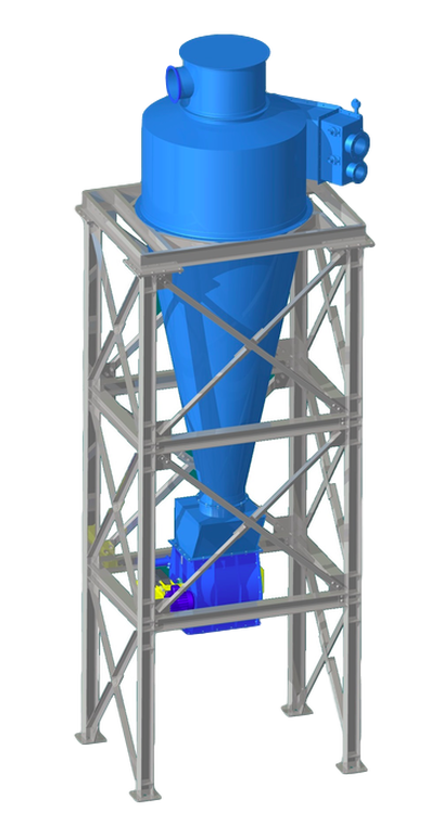
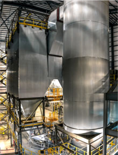
The high pressure cyclone is designed to accept high velocity air and material. An inlet impact liner, body liner and sometimes a cone liner is used to deal with the wear and abrasion caused by high speed materials entering the cyclone. The cyclone employs centrifugal separation, high speed air and dust is pushed to the interior of the cyclone, centrifugal forces separate air and material, material is discharges out the bottom and air discharged out the top. Cyclones are sized specifically for the system air volume, abrasion resistant materials are utilized for longer life of the cyclone.

