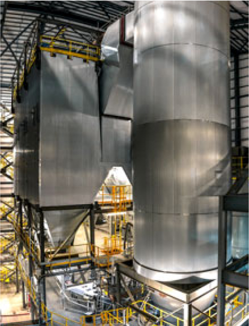
Thermal Oxidizer Technology
Thermal oxidizers are the primary technology used to destroy volatile organic compounds (VOCs), hazardous air pollutants (HAPs), and to some degree, odor. These pollutants are discharged as a result of industrial processes and can be destroyed by oxidation at a high temperature. Thermal oxidizers achieve emission destruction through the process of thermal and catalytic oxidation to convert pollutants into carbon dioxide and water vapor while at the same time reusing the thermal energy to reduce operating costs.
Catalytic oxidizers are simply thermal oxidizers with added catalyst that allow effective oxidation at a much lower temperature. In catalytic units the oxidation takes place on the surface of the catalyst. In contrast, in thermal oxidizers the oxidation takes place in the combustion chamber in the gas phase.
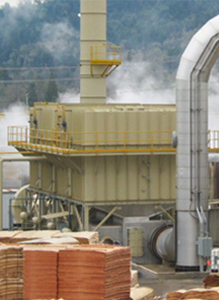
RCO Destruction Efficiency Up To 98% Thermal Efficiencies 95-97% Catalyst Selected to Match Application Requirements
Catalytic oxidizers come in the form of regenerative catalytic oxidizers (RCOs) and recuperative catalytic oxidizers. RCOs utilize beds of ceramic material to store and release thermal energy by reversing the process gas through alternate beds. Recuperative units utilize an internal gas to gas heat exchanger to continuously recover heat. Generally, RCOs are much more energy efficient than recuperative units. However, the recuperative approach may sometimes be the best choice particularly when the VOC concentration in the gas stream is high. On the other hand, in situations where the VOC concentration is low the RCO may be the better economic choice.
Optimizing Operating Efficiency
While the energy consumed in a catalytic oxidizer is less than half of a thermal oxidizer care must be taken in understanding the nature of the gas stream to be treated. Catalysts are very sensitive to certain compounds that may be present in the gas stream as they may “poison” the catalyst and render it ineffective. Also, the presence of particulate matter in the gas stream may have a masking effect with a similar negative result. A good rule of thumb is to be sure that the gases to be treated do not have poisons or particulates that would prevent the catalyst from operating effectively for at least five years.
Examples of applications in which RCOs are a good fit include printing and packaging processes where simple solvents such as alcohols, xylene and toluene are present. Also, wood products applications that do not include fly ash from wood combustion such as steam or gas heated veneer dryers are good applications.
A final consideration in choosing an RCO is the importance of periodic testing of the catalyst. Unlike RTOs the performance of an RCO is dependent on the activity of the catalyst as well as the operating temperature. Over time, an RCO catalyst tends to degrade in even the most benign applications. Therefore, it is important that a sample of the catalyst layer be removed on a periodic basis and sent to a qualified laboratory for testing. Typically, testing should be performed every three to five years.
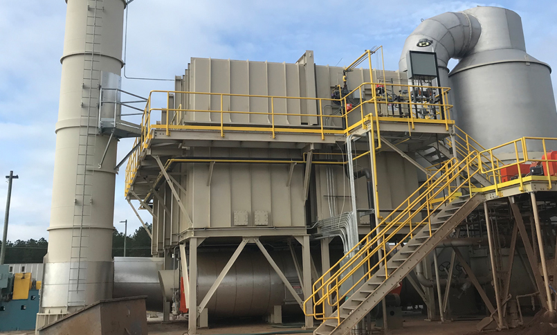
Thermal Oxidizer
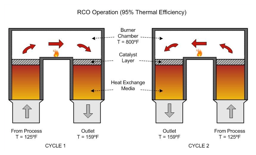
Basics Heat Recovery Chambers and Burner Chamber
While passing through the inlet heat recovery chamber, the emission stream is preheated to a temperature very near the burner chamber temperature. In the burner chamber, a natural gas burner maintains the temperature at approximately 800°F, the temperature required for complete thermal oxidation on the surface of the catalyst layer.
Upon exiting the burner chamber, the emission stream enters the outlet heat recovery chamber. The gas stream passes through the outlet heat transfer media bed where the heat energy gained from the inlet heat recovery chamber and burner chamber is transferred to the ceramic heat exchange media (heat sink). This is the final step in the regenerative process. Typical discharge temperatures from RCO systems are approximately 35°F above the inlet temperature. Finally, the emission stream exits the RCO system through the outlet diverter valve and is transferred to the stack via the induced draft fan.
Geoenergy® Single-Blade, Dual-Seat Poppet Valve
The dual-seat poppet valve offered is based on years of RCO experience with this design. The valve is very simple and robust with a minimum of moving parts. As illustrated, the valve allows process gas to pass in or out of the heat exchange media bed with a short stroke of the center shaft driven by an actuator mounted outside of the valve housing.
This valve design has been installed on more than 110 GeoTherm® RTO and GeoCat® RCO units operating on over 10,000,000 CFM of process gas.
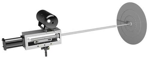
Geoenergy Single-Blade, Dual-Seat Poppet Valve
Features
Resistance to Organic Buildup
This feature is particularly important for gas streams containing condensable organics. Because the valve disc is heated by the outlet gas stream during each valve cycle, the valve is always hotter than the temperature of the inlet gas stream. This prevents condensation of organic compounds that buildup on the valves and seats.
Resistance to Solids Accumulation
With the valve disk and valve seat located approximately eight (8) inches above the floor of the housing, the unlikely occurrence of heavy deposits of solids do not interfere with the function of the valve.
Resistance to Deformation of Valve or Seat
Since the valve disk seats in both directions, (on both the inlet and outlet seats, ) the disk will not take a permanent set from seating in only one (1) direction.
GEOCAT® RCO SYSTEM BENEFITS
- Up to 98% thermal efficiency (TER)
- Catalyst selected to match application requirements
- Up to 99% destruction efficiency (DRE)
- Customized Ceramic Media Bed Configuration – plugging / chemical corrosion resistant
- Simple, fast-acting poppet valve design
- Resists condensation of organics on the poppet valve – valve remains hotter than the inlet gas stream, remaining free of buildup
- Minimal moving parts per Heat Recovery Chamber (HRC) – Only one (1) poppet valve per HRC, i.e., only two (2) valves per RTO
Industries Served
The Geoenergy® Brand
Our RCOs have been operating successfully for over 26+ years in some of the harshest process environments in the air pollution control industry, serving the industries of:
- Automotive
- Carbon Fiber
- Chemical Processing
- Engineered Wood Products
- Ethanol
- Fiber Manufacturing
- Fiberglass/Mineral Wood Insulation
- Flooring
- Foundry
- Insulation Manufacturing
- Oil & Gas
- Packaging & Printing
- Printing & Flexography
- Petrochemical
- Pharmaceutical
- Pulp & Paper
- Rendering
- Semiconductor
- Styrene
- Surface Finishing/Coating
- Tire Manufacturing
- Wastewater Treatment
- Wood Products
